| Sub types | |
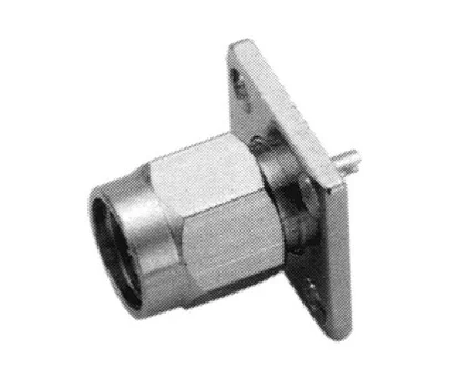
| V-7814 | Square flange Mount Jack Receptacle |
| Impedance | 50 ohm |
| Frequency Range | 0-12.4 GHz on flexible Cable 0-18 GHz on Semi- Rigid cable |
| Temperature Range | -65°C to +165°C |
| Electrical Characteristics | |
| Insulation resistance | 5000 Megaohms min. |
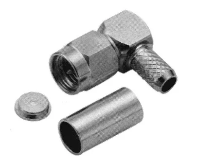
| V.S.W.R | Straight: 1.3 Max, R/A: 1.5 Max |
| Insulation loss | 0.3dB max @ 1.5 GHz ( Staight) 0.6dB max @ 1.5 GHz ( R/A) |
| Contact resistance | |
| Center Contact | 6 milliohms Max |
| Outer conductor | 2 milliohms Max |
| V.S.W.R | |
| Straight connector | 1.3 max |
| Right angle connector | 1.5 max |
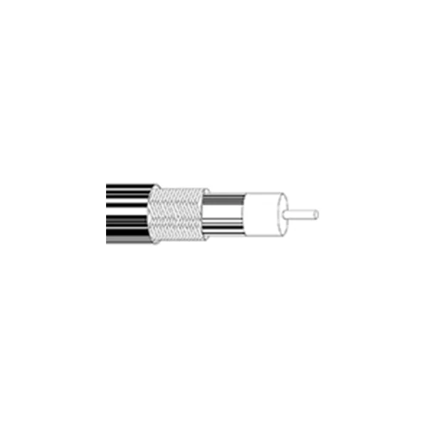
| Dielectric withstanding voltage in VRMS | RG178: 500 VRMS min. RG316,.85″: 250 VRMS max RG142,.141″: 335 VRMS max |
| Working voltage in VRMS( at sea level ) | – |
| Mechanical Characteristics | |
| Cabling retention force | RG58, 141, 142,223….> 40 lbs min RG178, 196… >6 lbs min |
| Force to engage and disengage | 2 in-lbms. Max |
| Coupling nut Torque recommended | 15 in-lbs min |
| Coupling nut retention force | 60 lbs. min |
| Environmental Characteristics | |
| Thermal Shock | MIL-STD-202 Method 107 Test Cond B |
| Corrosion (salt spray) | MIL-STD-202 Method 101 Test Cond B |
| Vibration | MIL-STD-202 Method 204 Test Cond B |
| Shock | – |
| Materials | |
| Body | Brass |
| Center contacts | |
| Female | Beryllium Copper or Brass |
| Insulator | Teflon |
| Finish | |
| Bodies | Nickel or Gold |
| Center contacts | Gold Plated |
| 12VDC power output | – |
| Downloads | |
| Datasheet (EN) | Download |
V-7814
محصولات مرتبط با V-7814


نقد و بررسیها
هنوز بررسیای ثبت نشده است.